
Please Choose Your Language
- All
- Product Name
- Product Keyword
- Product Model
- Product Summary
- Product Description
- Multi Field Search
TEL : +86-18920692288
Email : dwk0002025@163.com
Views: 0 Author: Site Editor Publish Time: 2026-07-20 Origin: Site


Sizing a bending machine requires matching material thickness, tensile strength, and bending length to the equipment's tonnage and physical dimensions. Selecting the wrong size carries severe operational penalties. Under-sizing leads to equipment damage and production bottlenecks. Over-sizing wastes capital, floor space, and electrical overhead.
Buyers often struggle to translate their daily material processing needs into correct machine specifications. You cannot rely on generalized, inaccurate rules of thumb to determine tonnage, bed length, and open height. Doing so risks catastrophic tooling failure or inefficient production cycles.
We will calculate exact tonnage requirements, evaluate drive technologies, and select a machine size. We balance current production realities, workflow efficiency, and future scalability.
Tonnage is Relative: Required tonnage is inextricably linked to material thickness, tensile strength, bending length, and the specific V-die opening used.
Length Limitations: The total bed length is not the maximum bending length; buyers must account for the distance between the side housings.
Bending Method Dictates Size: Air bending requires significantly less tonnage than bottoming or coining, directly impacting the required machine capacity.
Dimensional Clearances Matter: Tonnage and bed length are only part of the equation; daylight (open height), stroke length, and throat depth are critical for complex parts.
Future-Proofing Margin: Industry standard practice dictates adding a 20% to 30% capacity buffer to your maximum calculated tonnage to prevent machine fatigue and accommodate future material variations.
Tonnage represents the pressing force required to yield your material. You must understand how to calculate this force accurately to size your equipment. Manufacturers provide standard air bending force charts based on mild steel baselines. These charts typically assume a material tensile strength of 60,000 PSI.
You read these charts by cross-referencing your material thickness with your chosen V-die opening. The intersection provides the required tonnage per foot or meter. For example, bending 1/4-inch mild steel over a 2-inch V-die requires approximately 15.3 tons per foot. You then multiply this base figure by your total bending length. If you bend a 10-foot part, you need 153 tons of force just to yield the steel.
When operators try to push past these limits, the ram stalls. The hydraulic system hits its relief valve pressure. If you bypass safety valves, you risk snapping the punch or cracking the lower die right down the middle.
Mild steel serves as the baseline, but different materials require different force multipliers. You must adjust your calculations based on the specific alloy you process. Aluminum typically requires a 0.5x multiplier compared to mild steel. Stainless steel demands a much higher multiplier, generally ranging from 1.5x to 1.7x.
A36 mild steel behaves differently than AR400 wear plate. AR400 might require a 3.0x multiplier. Ignoring material hardness variations introduces significant risk. If you calculate tonnage based on mild steel but bend stainless, your machine will stall. Stalled bends damage tooling and cause excessive machine wear. Always calculate your maximum tonnage requirement based on the hardest material you plan to process.
Material Force Multiplier Reference
Material Type | Tensile Strength (Approx PSI) | Tonnage Multiplier (vs. Mild Steel) |
|---|---|---|
Soft Aluminum (e.g., 3003) | 20,000 - 30,000 | 0.50x |
Mild Steel (Baseline) | 60,000 | 1.00x |
Stainless Steel (e.g., 304/316) | 85,000 - 95,000 | 1.50x - 1.70x |
High-Strength Steel (e.g., AR400) | 150,000+ | 2.50x - 3.00x |
Buyers frequently confuse overall bed length with usable bending length. A 14-foot bed cannot bend a 14-foot part if that part features deep flanges. The side frames, or housings, physically block the material from passing through the sides of the machine.
You must calculate the true usable bending length based on your part geometry. Look at the specification for the distance between housings. If a machine has a 14-foot overall bed but only 12 feet between the housings, your maximum flanged part length is 12 feet. Shorter parts can utilize the full bed length if they do not interact with the side frames.
Sometimes operators try to bend off-center to clear a housing. This uneven loading damages the ram guides and hydraulic cylinders over time. You want the load centered. If your daily production involves 10-foot flanged parts, buy a machine with at least 10.5 feet between the housings.
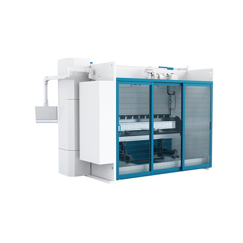
Tonnage dictates power, but dimensional clearances dictate capability. You must evaluate the physical space around the bending zone. A high-tonnage machine is useless if your part cannot physically fit between the upper beam and the lower bed.
Open height, often called daylight, is the maximum distance between the upper beam and the lower bed. This measurement determines the maximum height of your tooling and the depth of the parts you can form. Stroke length is the total distance the ram can travel vertically.
Deep box bending requires extended daylight. If you form four-sided electrical enclosures, the formed sides must clear the upper punch as the ram cycles. Tall punches and dies consume open height rapidly. Automated tool changers also require a press brake machine with extended daylight to maneuver tools in and out of the clamping system safely.
A short stroke limits how far the punch can retract. If you use tall gooseneck punches to clear deep return flanges, a short stroke traps the part against the tooling. You end up wrestling the sheet metal out sideways, scratching the finish and slowing down production. Always calculate your maximum box depth, add your punch height, die height, and material thickness. The resulting number must be less than your total open height.
The throat depth is the cutout in the side frames. It limits the maximum flange width you can bend when a long part extends past the side housings. If you bend a 14-foot part on a machine with 12 feet between housings, the ends of the part must enter the throat.
If your throat depth is 16 inches, your maximum flange on those extended ends is slightly less than 16 inches. Deeper throats offer more bending flexibility for oversized panels. However, a deeper throat reduces the overall rigidity of the machine frame. This trade-off requires careful consideration of your specific part geometries.
When you cut a deeper C-frame into the side housings, the machine naturally wants to yawn open under heavy loads. Manufacturers counter this by adding thicker steel plates to the frame, which increases the machine's footprint and weight. If you rarely bend parts longer than the distance between housings, stick to a standard throat depth to maximize frame rigidity.
Your tooling choices directly influence your machine sizing requirements. The lower die determines the leverage applied to the material. Changing the die opening changes the required tonnage drastically.
Industry standards dictate selecting a V-die opening that is eight times the material thickness. This rule applies primarily to mild steel up to 1/2 inch thick. The 8x ratio provides an optimal balance between required tonnage and the inside radius of the bend.
Decreasing the V-die opening exponentially increases the required tonnage. If you need a tighter inside radius, you must use a smaller die. Dropping from an 8x die to a 6x die can increase your tonnage requirement by 30% or more. You must size your machine to handle the tonnage required by your tightest required radii.
When you move past 1/2-inch plate, the rule shifts. You often need a 10x or 12x V-die opening to prevent the material from cracking on the outside of the bend. Wider dies reduce the tonnage requirement but increase the minimum flange length you can successfully bend.
The bending method you employ dictates the physical size of the machine you need. Air bending is the standard for most modern fabrication shops. The punch pushes the material into the die cavity without touching the bottom. Air bending requires the least amount of tonnage.
Bottoming forces the material against the sides of the V-die. This method requires three to five times the tonnage of air bending. Coining stamps the punch tip directly into the material, forcing it to conform exactly to the die shape. Coining requires five to ten times the tonnage of air bending. While rarely used today, legacy parts requiring coining necessitate a massive machine footprint.
Most shops air bend because modern CNC controls and precision ground tooling make it highly accurate. If you still bottom bend, you are buying significantly more machine capacity than necessary. Transitioning to air bending allows you to purchase a smaller, faster machine.
Tooling standards affect your precise tonnage calculations. Many high-quality tools are manufactured to metric standards. A nominal 0.250-inch V-opening is actually 6 millimeters, which equals 0.236 inches. This slight reduction in die opening increases the required tonnage.
You must account for these metric conversions when calculating maximum machine loads. Precision sheet metal shops must calculate forces based on the exact physical dimensions of the tooling, not just the nominal imperial labels.
Acute angle dies, offset dies, and hemming tools all change the force dynamics. Hemming, where you fold the metal flat against itself, requires massive tonnage at the very bottom of the stroke. If your daily work involves hemming, you need a machine rated for that specific bottom-stroke force.
The choice between American, European/Promecam, or Wila/Trumpf style tooling impacts machine sizing. American tooling traditionally uses a simple tang and setscrew system. Wila/Trumpf tooling utilizes hydraulic clamping and requires specific ram geometries.
European tooling often requires intermediate adapters. These adapters consume valuable open height. When sizing your machine, subtract the height of your chosen clamping system and adapters from the total daylight to determine your true usable working space.
Hydraulic clamping systems save hours of setup time every week. However, the clamping mechanism itself takes up vertical space. You must factor this into your daylight calculations. If you buy a machine with standard daylight and then add a tall hydraulic clamping system, you might not have enough room left for your actual punches and dies.
Machine size is not just about physical dimensions; it is about drive technology. The method used to move the ram affects speed, precision, and energy consumption. You must match the drive technology to your primary material types.
An electro hydraulic press brake machine is best for bending thick plate and long parts. This technology excels when processing 0.25-inch to 1-inch thick A36 steel. These machines utilize a traditional dual-cylinder design to generate massive force.
They offer high force capacity and extreme durability. They are typically slower than electric alternatives and require regular hydraulic fluid maintenance. You choose this technology when raw power, large bed lengths, and heavy plate processing are your primary sizing factors.
Modern proportional valves give these machines excellent control, but they still rely on moving large volumes of oil. The oil heats up during heavy production shifts, which changes its viscosity. This viscosity change can slightly alter the ram's stopping position. High-end models use oil chillers to maintain consistent temperatures and bending accuracy.
A precision press brake machine utilizing all-electric or hybrid drives is best for thin gauge materials. These machines dominate environments requiring high-speed production and extreme accuracy. They utilize servo motors and ball screws or belt-pulley systems instead of hydraulic cylinders.
Electric models offer lower tonnage caps, usually maxing out under 300 tons. They provide superior energy efficiency because motors only run when the ram moves. They deliver faster ram speeds and suffer zero hydraulic drift, making them ideal for aerospace or electronics components.
Hybrid machines combine servo motors with localized hydraulic pumps for each cylinder. You get the speed and energy efficiency of an electric machine with the power density of a hydraulic system. They eliminate the large central oil reservoir, reducing maintenance and environmental hazards on the shop floor.
A CNC press brake machine is essential for high-mix, low-volume production. These environments require rapid setups and strict precision requirements. The control system manages complex multi-bend operations seamlessly.
These machines integrate multi-axis backgauges to position complex parts accurately. They also feature automatic crowning systems. Crowning compensates for machine deflection on longer beds, ensuring consistent angles across the entire part length without manual shimming.
A basic 2-axis backgauge moves in and out (X-axis) and up and down (R-axis). If you bend complex, asymmetrical parts, you need a 4-axis or 6-axis backgauge. These systems allow the backgauge fingers to move independently, supporting tapered flanges and angled bends. The physical size of the backgauge assembly also requires space behind the machine.
Drive Technology Comparison
Technology Type | Best Material Thickness | Typical Tonnage Range | Key Advantage |
|---|---|---|---|
Electro Hydraulic | Medium to Heavy Plate (0.25" - 1"+) | 100 - 3000+ Tons | Maximum raw power and durability for heavy fabrication. |
All-Electric | Thin to Medium Gauge (Up to 0.25") | 20 - 300 Tons | High speed, extreme precision, and energy efficiency. |
Hybrid Servo-Hydraulic | Mixed Gauges | 100 - 600 Tons | Balances hydraulic power with servo-driven precision. |
Theoretical calculations must translate into practical machine selection. Examining specific production scenarios helps clarify how variables interact. We will look at two distinct fabrication requirements.
Consider a requirement to bend 12-inch wide, 0.25-inch thick A36 steel plate. We start with the base tonnage for 1/4-inch mild steel over a 2-inch V-die. This requires approximately 15.3 tons per foot. A 12-inch wide part is exactly one foot, so the base requirement is 15.3 tons.
However, processing heavy plate requires high frame rigidity. A long-bed machine will deflect too much for a short, thick part. The outcome here is to recommend a compact, high-tonnage machine. A 4-foot or 6-foot bed with a 100-ton capacity provides the necessary rigidity and concentrated force without wasting floor space.
You also need heavy-duty tooling. Standard gooseneck punches will shatter under these concentrated loads. You must specify straight, heavy-duty punches and multi-V dies designed specifically for thick plate fabrication.
Consider a requirement to bend 10-foot long, 11-gauge stainless steel. We find the base tonnage for 11-gauge mild steel, which is roughly 6 tons per foot. We then apply the stainless steel multiplier of 1.5x. This brings the requirement to 9 tons per foot. Over a 10-foot length, the total required force is 90 tons.
The outcome highlights the necessity of a 100+ ton machine. Furthermore, bending 10 feet of stainless steel guarantees significant frame deflection. Automated crowning is mandatory here to prevent the canoe effect, where the center of the bend under-forms compared to the edges.
The CNC control calculates the exact amount of deflection based on the material thickness, length, and tonnage. It then drives a motorized wedge system in the lower bed to push the center up by the exact millimeter required. This guarantees a perfect 90-degree bend from end to end.
Machine specifications represent only half of the sizing equation. You must evaluate how the equipment integrates into your physical facility. Ignoring infrastructure constraints leads to massive installation delays and cost overruns.
Large machines require specialized foundations. Equipment over 300 tons or exceeding 14 feet in length often requires reinforced concrete pads. Standard 6-inch factory floors will crack under the concentrated load of the side frames. Some high-tonnage models require deep pit mounts to keep the working bed at an ergonomic height.
You must factor in the required footprint for shop workflow. The machine dimensions are just the starting point. You need space for material handling equipment, such as overhead cranes or sheet followers. You must establish safety zones around the perimeter. If you plan future robotic automation, you need significant square footage in front of the machine.
Pouring a new foundation involves cutting the existing slab, excavating dirt, tying heavy rebar cages, and pouring high-PSI concrete. This process shuts down that area of your shop for weeks while the concrete cures. You must factor this downtime and construction expense into your sizing decision.
Electrical infrastructure often dictates machine viability. Traditional hydraulic systems draw continuous power. The main motor spins constantly to maintain hydraulic pressure, even when the ram is idle. This requires substantial, dedicated amperage.
Servo-electric models utilize on-demand power. They only draw peak current during the actual bending cycle. Upgrading to larger tonnage machines carries the risk of overloading undersized facility electrical panels. Always verify your available voltage and amperage against the machine's peak load requirements before finalizing a size.
If your shop experiences voltage drops when other heavy machinery starts up, the CNC control on a modern bending machine will throw error codes and shut down. You might need to install dedicated transformers or power conditioners to ensure clean, consistent voltage reaches the equipment.
Physics dictates that metal bends under pressure. As bed length and tonnage increase, the upper beam and lower bed will naturally deflect under load. They bow in the center, causing the punch to penetrate the die less in the middle than at the ends.
This deflection ruins part accuracy. Mechanical or CNC hydraulic crowning systems are non-negotiable for machines over 8 feet in length. Crowning pushes the center of the lower bed upward, perfectly countering the natural deflection. You must size your machine to include a robust crowning system to maintain precision requirements across long parts.
Without crowning, operators waste hours manually sliding paper or metal shims under the die to compensate for the bow. This manual shimming is inconsistent and destroys productivity. A built-in crowning system eliminates this wasted time entirely.
Sizing requires striking a delicate balance. Both extremes carry significant operational penalties. You must understand the costs associated with missing the optimal capacity target.
Buying a 400-ton machine to bend 16-gauge sheet metal is a costly mistake. Massive machines move slower. The heavy ram requires more time to accelerate and decelerate, resulting in slower cycle times. They consume more electricity and require larger volumes of hydraulic oil.
Over-sized machines waste valuable floor space. Furthermore, running thin materials on massive machines reduces tactile sensitivity for the operator. The control system struggles to maintain precise positional accuracy when applying minimal force with massive hydraulic cylinders.
If an operator makes a programming error on a massive machine while using delicate tooling, the machine will crush the tools before the safety limits engage. The sheer momentum of a heavy ram makes it difficult to stop instantly.
Under-sizing is equally dangerous. Running a machine at 100% of its rated tonnage daily accelerates mechanical wear. Hydraulic seals degrade faster under constant peak pressure. The machine frame experiences severe fatigue cycles.
Maxing out capacity risks catastrophic tooling failure. If material thickness varies slightly on the high side, a machine running at maximum capacity will stall. This stall can shatter punches or crack the lower die, creating severe safety hazards for operators.
Steel mills have tolerances. A sheet of 1/4-inch plate might actually measure 0.260 inches thick. It might also have a slightly higher carbon content than the last batch, increasing its yield strength. If your machine is already maxed out, these normal material variations will stop your production cold.
Industry best practices rely on a specific decision framework. Calculate the maximum tonnage required for your absolute worst-case part. Factor in the hardest material, the longest length, and the tightest V-die opening you will use.
Once you establish that baseline number, add 20% to 30% to determine your target machine size. This buffer prevents machine fatigue. It allows you to process materials that run slightly thicker or harder than their nominal mill specifications. This margin ensures your equipment remains capable as your business expands into new markets.
If you currently bend 10-foot parts but plan to bid on architectural jobs requiring 12-foot panels next year, size the machine for the 12-foot work now. Retrofitting a longer bed or adding tonnage later is physically impossible.
Audit your current and projected material processing needs, documenting maximum thickness, tensile strength, and longest part dimensions.
Calculate your exact tonnage requirements using the 8x V-die rule and apply the correct material multipliers for stainless or aluminum.
Measure your facility's physical constraints, including floor foundation thickness, electrical panel capacity, and available square footage for workflow.
Select a drive technology that aligns with your production volume, prioritizing servo-electric for high-speed thin gauge or electro-hydraulic for heavy plate.
Specify a machine with a 20% tonnage buffer and mandate an automatic crowning system for any bed length exceeding 8 feet.
A: Yes, but only if the machine features a throat depth (gap) in the side frames. The flanges on the extended ends of your part must be shorter than the depth of the throat to pass through the machine housings.
A: Stainless steel has a higher tensile strength and greater yield strength than standard mild steel. It resists deformation more aggressively. You typically need to multiply your mild steel tonnage calculations by 1.5 to 1.7 to successfully bend stainless alloys.
A: Decreasing the V-die opening creates a tighter inside bend radius but drastically increases the required tonnage. The narrower opening reduces the leverage the punch has on the material, forcing the machine to push much harder to achieve the yield point.
A: If your machine bed exceeds 8 feet in length, crowning is essentially mandatory for precision work. Without it, natural frame deflection will cause the center of your bends to be under-formed, resulting in inconsistent angles along the length of the part.
A: You must consult the machine manufacturer's foundation requirements and hire a structural engineer to core-test your floor. Machines over 300 tons typically require specialized, reinforced concrete pads to prevent the side frames from cracking standard factory floors.
A: It depends on your application. All-electric machines are superior for high-speed, high-precision bending of thin gauge materials due to their accuracy and energy efficiency. Hydraulic machines remain the better choice for raw power and heavy plate fabrication.


