
Please Choose Your Language
- All
- Product Name
- Product Keyword
- Product Model
- Product Summary
- Product Description
- Multi Field Search
TEL : +86-18920692288
Email : dwk0002025@163.com
Views: 0 Author: Site Editor Publish Time: 2026-08-03 Origin: Site


Metal forming has evolved from rudimentary manual bending to highly precise, CNC-controlled operations where micro-millimeters dictate part viability. Misunderstanding the underlying physics and mechanical limitations of a press brake machine leads to critical procurement errors. You might under-spec tonnage, mismatch drive types to your production volume, or experience excessive tooling wear that halts the line.
Evaluating an industrial press brake machine requires a foundational understanding of its mechanics, drive systems, and tooling dynamics. By analyzing how force is generated, controlled, and applied to sheet metal, fabrication facilities can accurately align their capital expenditure with actual production requirements. This prevents structural machine damage and ensures long-term part accuracy.
Physics Dictate Procurement: The choice between air bending, bottoming, and coining directly impacts the required tonnage and tooling specifications.
Drive Systems Define Efficiency: Hydraulic, electric, and hybrid drivetrains offer distinct trade-offs regarding speed, energy consumption, and maintenance overhead.
Tonnage is Non-Negotiable: Accurately calculating required force—and understanding when a high tonnage press brake machine is necessary—prevents structural machine damage and out-of-tolerance parts.
Safety is Integrated, Not Added: Modern press brakes rely on advanced optical and laser-safe systems that must be evaluated as core operational components, not aftermarket accessories.
A successful bending operation is defined by strict success criteria: dimensional accuracy, angular repeatability, and minimal material fatigue. Achieving a perfect bend requires controlling the immense physical forces acting upon the metal structure. Before evaluating machine specifications, you must understand the mechanical realities of forcing flat sheet metal into a permanent three-dimensional shape.
The fundamental bending sequence follows a precise mechanical action on the shop floor. The process breaks down into a specific cycle:
The operator or robotic cell slides the flat material against the backgauge fingers to establish the exact bend line.
The material is clamped between the upper punch and the lower die as the ram descends.
Force is applied via the bending beam, driving the punch into the material to achieve a predetermined angle.
The ram retracts, releasing the permanently shaped part while the material undergoes springback.
During this sequence, the material undergoes severe internal stress. The neutral axis of the sheet metal represents the theoretical line within the material thickness where neither compression nor tension occurs. As the punch forces the metal into the die, the inner radius of the bend undergoes intense compression. Simultaneously, the outer radius expands and stretches. This expansion leads to material elongation and the phenomenon known as springback. Because the material attempts to return to its original flat state after the forming pressure is released, the machine must overbend the metal slightly to achieve the target resting angle. The material's yield strength, tensile strength, and thickness dictate exactly how much bending force is required to surpass its elastic limit.
The mechanical behavior of thin-gauge sheet metal differs drastically from heavy metal plate. Thin materials require high precision, fast ram speeds, and rapid backgauge movements to maintain high throughput. Heavy plate forming exponentially increases the demand on the machine's structural rigidity. Bending thick plate generates massive upward force on the ram and downward force on the bed, requiring heavy-duty frames to prevent deflection.
Different forming methods also dictate machine requirements. Air bending is the most common method in modern fabrication. The punch presses the material into the die cavity without bottoming out. The bend angle is determined entirely by how deep the punch descends into the V-die. This method requires less tonnage and relies heavily on CNC precision and linear encoders to control ram depth.
Bottom bending forces the material completely against the die angle. The punch pushes the sheet metal until it makes full contact with the sides of the V-die. This yields higher angular accuracy but requires significantly higher tonnage to overcome material springback. Coining, or forging, stamps the punch tip directly into the material, compressing the metal and permanently altering its internal molecular structure. This eliminates springback entirely but requires massive, destructive levels of tonnage. Coining is rarely used in modern precision fabrication due to the extreme wear it causes on machinery and tooling.
Forming Methods Comparison
Forming Method | Tonnage Requirement | Tooling Contact | Primary Advantage |
|---|---|---|---|
Air Bending | Low to Moderate | Three points (punch tip, two die shoulders) | Flexibility to form multiple angles with one die |
Bottom Bending | High | Full contact with die faces | Excellent angular consistency |
Coining | Extreme | Full compression of material structure | Zero springback |
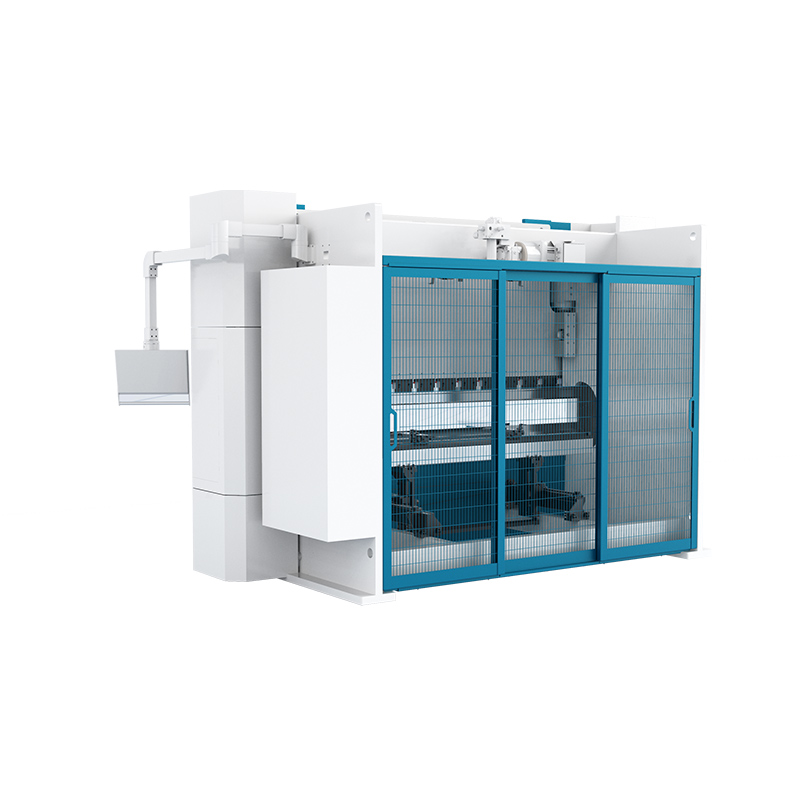
Understanding machine performance requires breaking down the core mechanical components that generate, control, and measure force. The drivetrain and ram are responsible for force generation. Momentum must be controlled precisely, transferring energy smoothly through the drivetrain to the bending beam. Modern systems utilize high-resolution linear encoders mounted on independent side frames. These encoders monitor the ram position to the micron level, feeding real-time data back to the controller to ensure the ram descends evenly, regardless of where the material is placed along the bed.
The punch and die tooling systems are the physical interface between the machine and the material. The upper tool and lower V-die must be perfectly matched to the material thickness and desired bend radius. The punch tip radius directly influences the inner radius of the bent part, while the V-die opening determines the leverage applied to the metal. Various tooling profiles serve specific mechanical applications. Gooseneck punches allow for deep channel bending without colliding with previously formed flanges. Acute punches are used for sharp angles or as a preliminary step for hemming operations. Sash punches provide clearance for complex, multi-bend profiles.
The backgauge system provides the precision and repeatability necessary for production environments. Multi-axis CNC backgauges utilize several axes to position the material accurately before the ram descends:
X-Axis: Moves the backgauge fingers forward and backward to control the depth of the flange.
R-Axis: Adjusts the vertical height of the backgauge fingers to accommodate different die heights and complex part geometries.
Z1 and Z2 Axes: Move the fingers laterally along the bend length to support varying part widths and asymmetrical blanks.
The rigidity and travel speed of the backgauge directly impact overall cycle times. A fast, vibration-free backgauge allows operators to sequence complex parts rapidly without waiting for the machine to catch up. CNC controllers and software serve as the brain of the operation. Modern controllers calculate complex bend allowances, predict springback based on material libraries, and determine optimal bending sequences from imported 3D CAD models. This computational power prevents tool collisions and reduces setup times from hours to minutes.
The mechanism driving the ram dictates the machine's speed, energy consumption, and maintenance profile. Fabricators must evaluate the three primary drive mechanisms to match machine capabilities with production demands.
Hydraulic systems remain the industry standard for general fabrication. These machines utilize dual hydraulic cylinders mounted on the side frames to drive the ram downward. The primary advantage of hydraulic systems is their high force capacity and proven, rugged reliability. They offer a lower initial capital cost compared to electric alternatives. However, hydraulic systems rely on continuous-running motors to maintain fluid pressure, resulting in constant energy consumption even when the machine is idle. They also require regular hydraulic fluid maintenance, filter changes, and are susceptible to thermal drift. As hydraulic oil heats up during a long shift, its viscosity changes, which can slightly alter ram positioning accuracy if the machine lacks advanced thermal compensation.
Electric systems prioritize high speed and low maintenance. These machines replace hydraulic cylinders with heavy-duty servo motors connected to ball screws or advanced belt-and-pulley systems. The mechanical advantages are significant: extreme precision, rapid acceleration and deceleration, and exceptional energy efficiency. Electric motors only draw power when the ram is actively moving, drastically reducing electrical overhead. Furthermore, the complete elimination of hydraulic fluid removes the risk of leaks and reduces maintenance downtime. The primary limitations of electric drives are their generally lower maximum tonnage capacities and a higher upfront acquisition cost.
Hybrid systems offer a balance of efficiency and power. Servo-hydraulic drivetrains use independent electric servo motors to drive specialized hydraulic pumps mounted directly above each cylinder. The pumps only activate when movement is required, combining the heavy-duty force generation of hydraulics with the energy efficiency and quiet operation of electric drives. This configuration minimizes the volume of hydraulic oil required and significantly reduces thermal drift. Hybrid systems are often evaluated as the optimal middle ground for high-mix, high-volume environments that require both substantial bending power and precise control.
Drive System Comparison
Drive Type | Force Generation | Energy Efficiency | Maintenance Overhead | Best Application |
|---|---|---|---|---|
Hydraulic | Dual fluid cylinders | Low (Continuous run) | High (Oil, filters, seals) | Heavy plate, general fabrication |
Electric | Servo motors & ball screws | High (Power on demand) | Low (No fluid, minimal wear) | High-speed precision sheet metal |
Hybrid | Servo-driven hydraulic pumps | High (Power on demand) | Medium (Reduced oil volume) | High-mix, variable tonnage production |
Determining the correct machine size requires strict mathematical evaluation based on material specifications. Tonnage is the absolute measure of bending force, and underestimating this requirement leads to stalled rams, damaged tooling, and compromised machine frames.
The relationship between the V-die opening and material thickness is the foundation of tonnage calculation. The standard industry rule of thumb dictates that the V-die opening should be exactly eight times the material thickness for bending mild steel. Changing the V-die opening inversely affects the required tonnage. Using a wider V-die reduces the required force but increases the internal bend radius. Conversely, forcing material into a narrower V-die achieves a tighter radius but exponentially increases the tonnage demand. Operators must calculate the required force per foot of bend length based on the material's specific tensile strength.
Knowing when to specify a high tonnage press brake machine is critical for heavy industrial applications. Production scenarios involving thick metal plate, high-tensile materials like Hardox or Domex, or exceptionally long bend lengths require massive force. When operating at high tonnage, the physical frame of the machine will naturally deflect under the load. To counteract this, heavy-duty machines require advanced crowning systems. Crowning utilizes mechanical wedges or hydraulic cylinders built into the lower bed to push upward during the bend, compensating for the machine's natural deflection and ensuring the bend angle remains consistent from the ends of the part to the center.
Consider the operational envelope of a 320 ton press brake machine. A unit of this size is typically capable of air bending 1/2-inch mild steel plate over a full 10-foot bed length using a standard V-die. Operating at this capacity introduces specific facility requirements. The physical weight of the material demands overhead cranes or heavy-duty sheet followers to assist the operator. Tooling at this tonnage level is significantly heavier and wider, often requiring specialized lifting equipment just to perform tool changeovers. The machine frame itself will weigh tens of thousands of pounds, necessitating specific foundation depths to maintain structural alignment.
High-force machinery presents inherent dangers, specifically the risk of operator crushing injuries. Modern mechanics mitigate these risks through integrated, highly responsive safety systems that do not impede production speed.
Light curtains and laser-safe systems are the primary defense mechanisms. Advanced optical safety systems project continuous laser fields just millimeters below the punch tip. As the ram descends in high-speed approach mode, the laser field travels with the tool. If a foreign object breaks the beam, the system triggers an immediate halt. The machine's braking response time is measured in milliseconds, stopping the ram instantly before contact is made. Modern systems allow for intelligent blanking, where the laser recognizes the profile of a box or tray being bent and ignores the pre-formed flanges that interrupt the beam, allowing the bend to proceed safely.
Operator ergonomics also play a critical role in risk mitigation. Bending large, heavy metal plates causes the material to swing upward rapidly as the punch enters the die. This whiplash effect can easily cause severe operator strain or blunt force trauma. CNC-controlled sheet followers are mechanical arms mounted to the front of the machine that rise in perfect synchronization with the bending angle, supporting the weight of the material and protecting the operator. Evaluating these systems ensures compliance with strict OSHA, ANSI, and CE standards that dictate machine safety configurations and stopping distances.
Bridging the gap between machine mechanics and facility readiness ensures a successful installation. A machine's physical footprint, foundation requirements, and power draw must align with the building's infrastructure.
High tonnage machines require specialized concrete foundations to prevent settling and maintain bed alignment. A standard six-inch shop floor will crack under the concentrated weight and dynamic load of a heavy-duty machine. Facilities often need to excavate and pour reinforced concrete pads, sometimes several feet deep, incorporating isolation materials to dampen vibration. Power requirements also vary drastically. Continuous hydraulic pumps require heavy electrical busbar setups to handle high inrush currents during motor startup, whereas servo-electric drives may require cleaner, stabilized power feeds to protect sensitive electronics.
Tooling compatibility and setup times directly impact operational throughput. Facilities must evaluate the mechanical trade-offs between tooling styles. European precision tooling offers highly accurate, ground finishes with self-centering profiles. Wila/Trumpf style tooling allows for vertical loading and unloading, drastically reducing setup times for heavy punches. Traditional American tooling is rugged and capable of handling high tonnage but often requires manual alignment. To reduce changeover times in high-mix environments, hydraulic or pneumatic tool clamping systems are implemented. These systems secure the entire length of the punch and die with the push of a button, replacing the labor-intensive process of manually tightening individual set screws.
Conduct a comprehensive time study on your most complex parts to determine if multi-axis CNC backgauges will eliminate production bottlenecks.
Calculate your exact tonnage requirements using the specific yield strengths and maximum bend lengths of the hardest materials in your inventory.
Request physical test bends from manufacturers using your actual material grades to verify angular repeatability and springback compensation before finalizing procurement.
Audit your facility's concrete foundation depth and electrical infrastructure to ensure it can safely support and power heavy-duty machinery.
A: Mechanical brakes use a continuously spinning flywheel and clutch system to drive the ram, offering high speed but limited control. Modern hydraulic systems use fluid-driven cylinders regulated by CNC valves, providing precise control over ram speed, position, and applied force throughout the entire bending cycle.
A: Tonnage is calculated using a formula that factors in the material's tensile strength, the material thickness squared, and the length of the bend, divided by the width of the V-die opening. Using a wider V-die reduces the required tonnage but increases the internal bend radius.
A: Springback occurs because the outer radius of the bend is stretched while the inner radius is compressed. When the forming pressure is released, the material's natural elastic properties cause it to attempt to return to its original flat state, requiring the machine to slightly overbend the target angle.
A: When immense force is applied during a long bend, the center of the machine bed naturally deflects downward, while the center of the ram deflects upward. Crowning systems push the center of the lower bed upward to compensate for this deflection, ensuring the bend angle remains perfectly consistent from end to end.
A: A multi-axis backgauge allows the machine to automatically position the material for complex, multi-step parts without operator intervention. The X-axis controls flange length, the R-axis adjusts vertical height for different die sizes, and the Z-axes move laterally to support varying part widths, drastically reducing setup time.
A: While electric servo-driven brakes are highly precise and efficient, they are generally limited to lower tonnage applications, typically under 150 tons. Bending thick, heavy metal plate usually requires the massive force generation capabilities of hydraulic or heavy-duty hybrid drive systems.


