
Please Choose Your Language
- All
- Product Name
- Product Keyword
- Product Model
- Product Summary
- Product Description
- Multi Field Search
TEL : +86-18920692288
Email : dwk0002025@163.com
Views: 0 Author: Site Editor Publish Time: 2026-07-27 Origin: Site


Modern metal fabrication demands strict control over cycle times, setup efficiency, and energy consumption. Selecting a press brake based solely on upfront cost or legacy familiarity often creates operational bottlenecks. You might struggle to hold tolerances on complex, high-tensile materials or deal with excessive power draw. We see shops constantly over-specifying machines, wasting floor space, or under-specifying and damaging frames. You need to match the machine's architecture to the actual parts you bend daily. Whether you process thin-gauge aluminum enclosures or heavy structural steel plates, the drive mechanism and control system dictate your throughput. To optimize bending operations, fabricators must evaluate drive systems, tonnage capacities, and CNC integration against their specific production mix. This guide breaks down the technical realities of modern bending configurations to support capital equipment purchasing decisions.
Drive System Alignment: Electric and hybrid systems dominate high-mix, precision-critical environments, while hydraulic systems remain the standard for heavy-duty, high-tonnage applications.
Tonnage Realities: Over-specifying tonnage wastes capital and floor space; under-specifying leads to machine damage and compromised bend accuracy. Benchmark capacities like a 100 ton press brake and a 160 ton press brake serve specific material and length thresholds.
CNC Integration: The true ROI of a modern machine lies in its control system—offline programming, automated crowning, and multi-axis backgauges drastically reduce setup times and operator dependency.
Machine selection begins with a strict audit of your daily production requirements. You cannot evaluate hardware without defining the exact materials and geometries your operators handle every shift. Different metals behave differently under load. Tensile strength dictates the force required to yield the material. A 50,000 PSI yield strength mild steel requires significantly less force than a 100,000 PSI high-tensile alloy. Thickness variations across a single sheet require dynamic machine compensation to maintain accurate angles. Springback forces operators to overbend parts, requiring precise control over ram depth.
Production volume heavily influences machine architecture. High-volume, low-mix environments demand raw speed. These shops benefit from automated part handling, robotic integration, and fast ram approach speeds. Conversely, high-mix, low-volume environments prioritize setup reduction. Job shops need machines that transition quickly between entirely different parts. They require intuitive controls, multi-axis backgauges, and rapid-clamping tooling systems. If your operators spend two hours setting up a machine for a ten-minute production run, your equipment architecture is failing your business model.
Tolerance requirements also dictate machine specifications. Downstream assembly processes demand specific baseline accuracy. Robotic welding cells cannot accommodate inconsistent bend angles. If a flange is off by two degrees, the welding robot will miss the joint entirely, creating expensive scrap. You must align your bending accuracy with your assembly requirements. Tight tolerances demand rigid machine frames, active crowning systems, and high-resolution linear encoders that monitor ram position down to the micron.
Operator ergonomics directly impact cycle times. Bending large, heavy panels manually causes operator fatigue. This slows production and increases safety risks. You must assess how operators interact with the workpiece during the bending cycle. Sheet followers and ergonomic part supports reduce physical strain. A comfortable operator maintains consistent cycle times throughout a long shift, reducing the likelihood of dropped parts or repetitive motion injuries.
Hydraulic systems rely on fluid dynamics to generate bending force. A CNC hydraulic press brake utilizes heavy-duty hydraulic cylinders and proportional directional valves to drive the ram. Computer numerical control synchronizes these cylinders, reading feedback from glass scales to ensure the ram remains parallel to the bed during the bend.
These machines deliver massive power density. They easily achieve extreme tonnages necessary for heavy plate fabrication. They typically present a lower initial capital requirement compared to fully electric alternatives. However, traditional hydraulic systems run their pump motors continuously. This draws power while the machine sits idle during part handling or setup. Hydraulic fluid also heats up over a long shift. This thermal expansion changes the viscosity of the oil, which can cause slight variations in ram positioning accuracy. Operators must manage ongoing fluid maintenance, filter changes, and leak prevention.
Hydraulic machines excel in heavy plate fabrication. They dominate environments bending thick mild steel, AR400, or structural components. They remain the standard choice when brute force supersedes micro-millimeter precision.
Electric machines eliminate hydraulic fluid entirely. They employ high-torque servo motors driving precision ball screws or heavy-duty belt-and-pulley systems to move the ram. This direct mechanical linkage provides exceptional control over ram position and velocity.
Servo-electric systems offer instantaneous acceleration and deceleration. They deliver extreme repeatability, often holding ram position within 0.0001 inches. They operate quietly, improving the shop floor environment. Because the motors only draw power when the ram actually moves, electric machines consume up to 50% less energy than continuous-run hydraulic systems. They eliminate oil changes, leak hazards, and thermal drift issues completely.
The primary limitation is capacity. Electric machines rarely exceed 300 tons. They also require a higher initial acquisition investment. These machines dominate precision sheet metal work. They are ideal for 16-gauge enclosures, intricate electronic chassis, and facilities facing strict energy or noise compliance mandates.
Hybrid systems bridge the gap between pure hydraulic and pure electric architectures. They use AC servo motors to drive independent, closed-loop hydraulic pumps mounted directly on each cylinder. The servo motor only spins when the CNC commands ram movement.
This design offers the high tonnage capabilities of traditional hydraulics alongside the energy efficiency of electric systems. Hybrids generate significantly less heat, drastically reducing thermal drift. They offer faster approach and retract speeds than conventional hydraulics. The architecture is slightly more complex, requiring maintenance personnel to understand both servo drives and localized hydraulic circuits.
Mid-to-heavy fabricators choose hybrid systems to reduce operational overhead without sacrificing bending capacity. They provide a versatile middle ground for shops handling a wide variety of material thicknesses.
Legacy mechanical machines use a massive spinning flywheel engaged by a clutch to drive the ram downward. Once the clutch engages, the ram completes its full stroke. Operators cannot stop or reverse the ram mid-stroke. Modern safety standards and precision requirements have largely rendered pure mechanical flywheel systems obsolete.
Up-acting systems flip the traditional bending motion. The upper beam remains stationary while hydraulic cylinders push the lower bed upward. This design offers niche ergonomic advantages. Operators can rest large, flexible panels against the stationary upper die before initiating the bend. This prevents the material from whipping upward, reducing operator fatigue and improving safety on specific large-panel applications.
Drive System Comparison Matrix
Drive Type | Primary Advantage | Primary Limitation | Ideal Application |
|---|---|---|---|
CNC Hydraulic | High tonnage capacity at lower initial cost | Continuous energy draw, thermal drift | Heavy plate, structural steel |
Servo-Electric | Extreme precision, low energy usage | Tonnage capped around 300 tons | Precision sheet metal, electronics |
Hybrid | Combines high tonnage with energy efficiency | Complex maintenance requirements | High-mix mid-to-heavy fabrication |
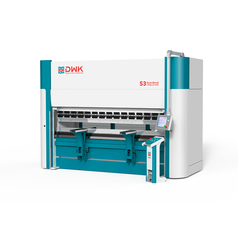
Tonnage dictates what a machine can physically bend. Specifying the right capacity requires understanding the bending method. Air bending requires the least amount of force. The punch pushes the material into the V-die cavity without bottoming out. The final angle depends entirely on the depth of the punch penetration. Bottoming forces the material fully into the die, requiring roughly three to five times more tonnage than air bending. Coining stamps the punch tip directly into the material to eliminate springback, demanding up to ten times the air bending tonnage.
The V-die ratio mathematically determines the required force. A standard rule for mild steel dictates a V-die opening eight times the material thickness. Narrowing the V-die opening allows for a tighter inside radius but drastically increases the required tonnage per foot. Fabricators must calculate the force required for their thickest material over their longest required bend length. You must also account for grain direction. Bending against the grain requires more force than bending with the grain.
Standard Mild Steel Tonnage Requirements per Foot (Air Bending)
Material Gauge / Thickness | Recommended V-Die Width | Approximate Inside Radius | Force Required (Tons/Ft) |
|---|---|---|---|
16 Gauge (0.060") | 0.500" | 0.090" | 4.5 |
10 Gauge (0.135") | 1.125" | 0.180" | 11.0 |
1/4 Inch (0.250") | 2.000" | 0.312" | 15.5 |
3/8 Inch (0.375") | 3.000" | 0.500" | 25.0 |
A 100 ton press brake serves as the workhorse for standard job shops. This capacity benchmark typically handles up to 10-gauge mild steel over a full 10-foot bed using standard air bending techniques. It provides ample force for most light-to-medium fabrication tasks without drawing excessive power.
This capacity hits the application sweet spot for HVAC components, electrical enclosures, and architectural metalwork. It balances adequate bending power with a relatively compact facility footprint. These machines generally feature faster ram approach and retract speeds than heavier models, maximizing throughput on lighter gauge parts. Over-specifying a machine for thin materials wastes floor space and slows down production, as heavier rams simply cannot move as quickly.
When production shifts toward structural components, a 160 ton press brake becomes necessary. This capacity benchmark easily handles 1/4-inch mild steel over a 10-foot bed. It also provides the concentrated force required to bend thicker materials over shorter spans.
Heavy equipment manufacturing, agricultural machinery, and commercial transport fabrication rely on this tonnage class. High-tensile materials like AR400 or Hardox require significantly more force to yield than standard mild steel. Stepping up to this tonnage necessitates robust frame construction. The side frames and bed must resist extreme bending forces to prevent yaw and deflection. A weak frame under high tonnage will permanently deform, destroying the machine's baseline accuracy and requiring expensive recalibration or replacement.
Some applications require bending parts longer than 20 feet. Single machines of this length suffer from extreme bed deflection. They also present prohibitive shipping and installation challenges. Tandem configurations solve this problem by linking multiple frames.
Tandem setups synchronize two or more machines to operate as a single, ultra-long unit. The CNC perfectly matches the ram positions of both machines, reading feedback from all linear encoders simultaneously. Fabricators use tandem setups for manufacturing light poles, commercial transport trailers, and aerospace components. When not bending massive parts, operators can decouple the machines and run them independently, doubling the shop's capacity for shorter parts.
Under heavy load, the machine ram bows upward in the center, and the bed bows downward. This physics phenomenon is known as deflection. Without compensation, deflection causes the punch to penetrate less in the center of the part than at the ends. This creates a "canoe" effect, where the bend angle is tighter at the edges and open in the middle.
Crowning systems counteract this deformation. Manual crowning requires operators to adjust wedges or shims beneath the die holder. This wastes time and relies on trial and error. Modern operations require automated, CNC-controlled crowning. The CNC calculates the expected deflection based on material thickness, length, and tensile strength. It automatically adjusts hydraulic cylinders or motorized mechanical wedges within the bed to push the center upward, ensuring parallel deformation across the entire bend length.
The backgauge positions the material accurately before the ram descends. A basic 2-axis backgauge controls the X-axis (forward and backward) and the R-axis (up and down). This suffices for simple, straight bends on flat panels.
Complex, asymmetrical, or staged bending requires advanced 4-to-6-axis configurations. These systems add independent control for the left and right gauge fingers (Z1, Z2) and independent depth control (X1, X2). Multi-axis backgauges eliminate manual part marking. They allow operators to stage multiple different tooling setups across the bed and move the part seamlessly between them. This drastically reduces operator handling time and slashes overall cycle times.
The punch and die dictate the final part geometry. Specific punch and die sets create predetermined angles and internal radii. Tooling styles vary regionally and functionally. American traditional tooling uses a simple tang and setscrew clamping method, requiring manual seating. European precision tooling features a safety groove and allows for faster, more accurate seating. Wila/Trumpf style tooling offers the highest precision and fastest tool changes, utilizing a proprietary button-release mechanism for vertical loading.
Automated clamping systems deliver massive throughput gains in high-mix environments. Manual clamping requires operators to tighten individual bolts across the entire ram. Hydraulic or pneumatic push-button clamping secures all punches and dies simultaneously in seconds. This technology slashes setup times, allowing job shops to profitably run small batch sizes.
Installing heavy fabrication equipment requires rigorous facility preparation. You must assess your floor foundation requirements. High-tonnage machines concentrate massive weight on a small footprint. Standard concrete slabs often crack under this point load. You may need to excavate and pour reinforced concrete pads specifically designed for the machine's footprint, complete with isolation material to prevent vibration transfer. You must also verify power drops and ensure adequate amperage. Hydraulic machines generate heat, requiring ambient temperature controls or dedicated oil chillers to maintain fluid viscosity during summer months.
Safety and compliance present ongoing operational challenges. You must navigate OSHA and ANSI standards. Traditional light curtains create a safety barrier, but they often interfere with the bending of complex parts with side flanges. Operators frequently mute light curtains to finish complex bends, defeating the safety mechanism entirely. Modern laser safeguarding systems, such as LazerSafe, mount directly to the ram. The laser travels just below the punch tip. This allows operators to hold parts close to the tooling while maintaining full safety compliance, significantly improving efficiency on complex geometries.
Tooling compatibility represents a major hidden cost. Upgrading a machine often means upgrading the ram clamping system. If your existing tooling inventory uses American tangs, but your new machine features a European precision clamping system, your old tools become useless. You must factor the cost of tooling adapters or a complete tooling replacement into your capital equipment budget before signing a purchase order.
The choice of bending equipment hinges on a strict analysis of your material mix, required tolerances, and operational overhead. There is no universal best machine. You must find the correct architectural fit for your specific production environment. Electric machines dominate precision sheet metal, while heavy hydraulics rule the structural plate sector.
Fabricators should build RFQs based on their 80th percentile jobs. Do not over-capitalize by buying a massive machine just to handle extreme outlier jobs that occur twice a year. Size the equipment for the work you do every single day.
Take the following steps to finalize your equipment strategy:
Audit your current production mix to identify the exact material thicknesses and lengths that make up 80% of your daily volume.
Measure your existing tooling inventory to determine compatibility with new clamping systems before finalizing a machine specification.
Consult with a structural engineer to verify your shop floor can support the point load of a high-tonnage machine.
Request time studies from equipment manufacturers using your specific part files to validate actual cycle time improvements.
A: Hydraulic machines use fluid-driven cylinders, offering massive tonnage capacity for heavy plate but consuming more energy. Electric machines use servo motors and ball screws. They consume up to 50% less energy, operate quietly, and deliver extreme precision, but are typically limited to capacities under 300 tons.
A: You calculate force based on material thickness, tensile strength, bend length, and the V-die opening. A standard rule for mild steel requires a V-die opening eight times the material thickness. Narrowing the die increases the required tonnage per foot significantly. Always size for your thickest, longest parts.
A: This capacity typically handles up to 10-gauge mild steel over a full 10-foot bed using standard air bending techniques. It provides ample force for HVAC components, electrical enclosures, and lighter precision sheet metal work without requiring a massive facility footprint.
A: Shops need this capacity when bending 1/4-inch mild steel over a 10-foot bed, or when working with high-tensile materials like AR400 over shorter spans. This tonnage suits structural components, heavy equipment manufacturing, and thick plate fabrication where lower-capacity machines would stall or suffer frame damage.
A: It integrates computer numerical control with hydraulic cylinders. The CNC precisely manages proportional directional valves, ensuring the hydraulic cylinders move synchronously. This provides automated precision, programmable ram depths, and exact repeatability across complex bending sequences, replacing manual depth stops.
A: Under heavy load, the machine frame deflects, causing the center of the bed to bow downward. Automated crowning uses CNC-controlled mechanical wedges or hydraulic cylinders to push the center of the bed upward. This compensates for deflection, ensuring a consistent bend angle across the entire part length.


