
Please Choose Your Language
- All
- Product Name
- Product Keyword
- Product Model
- Product Summary
- Product Description
- Multi Field Search
TEL : +86-18920692288
Email : dwk0002025@163.com
Views: 0 Author: Site Editor Publish Time: 2026-08-17 Origin: Site


Transitioning from manual bending to automated forming requires a fundamental shift in how operators interact with the machine. Unlike manual brakes, a CNC press brake uses a computerized control system to manage all critical functions—ram motion, backgauge positioning, bending speed, and pressure—prioritizing software inputs and systematic setup over manual adjustments. Inconsistent operator training on high-tonnage equipment leads to high scrap rates, tooling damage, and severe safety liabilities. Shop managers need standardized, repeatable workflows to bring beginner operators up to speed without risking production bottlenecks. This guide details the essential operational phases of a CNC press brake—from pre-operation inspection and tooling installation to controller programming, first-article execution, and routine shutdown—providing a framework for safe, efficient, and scalable metal fabrication.
Standardized Setup is Critical: Proper pre-operation inspection and precise tooling alignment prevent catastrophic machine damage and ensure baseline accuracy before the first bend.
Controller Programming Dictates Yield: Modern CNC controllers manage ram motion, bending speed, and backgauge positioning; accurate input of material parameters (thickness, tensile strength) is non-negotiable for minimizing scrap.
Tonnage Must Match Application: Operating a 100 ton CNC press brake requires different tooling load calculations than a 160 ton machine; exceeding tooling capacity limits causes permanent deformation.
Safety Systems are Mandatory: Integration and proper use of light curtains and laser safeguarding systems are required to mitigate the inherent risks of hydraulic press brake operation.
Computerized numerical control systems dictate all critical machine functions. They replace manual mechanical stops with multi-axis automated control. The Y1 and Y2 axes govern the left and right hydraulic cylinders. They ensure the ram descends parallel to the bed. The X, R, and Z axes control the backgauge positioning. This multi-axis control allows operators to form complex profiles without manually resetting stops between bends.
A continuous feedback loop exists between the hydraulic proportional valves and the linear scales. Linear scales read the exact position of the ram down to the micron level. They send this data back to the controller instantly. The controller then adjusts the proportional valves to maintain perfect synchronization. This guarantees precise bending speeds and accurate pressure application across the entire bending length. In a busy fabrication shop, this means a setup that used to take twenty minutes on a manual machine now takes less than two minutes. The operator simply calls up the program, and the machine positions itself.
Machine capacity dictates your operational limits and maximum material thickness. Tonnage represents the maximum bending force the machine can safely apply. You must calculate the required bending force for every job before pressing the foot pedal. Exceeding the machine's capacity damages the frame, the hydraulic system, and the tooling.
Different fabrication tasks require specific machine capacities. A 100 ton CNC press brake handles standard sheet metal enclosures, brackets, and light-gauge panels perfectly. It offers speed and agility for thinner materials like 16-gauge or 11-gauge mild steel. Conversely, processing thick steel plate requires more force. A 160 ton CNC hydraulic press brake provides the necessary power to fold thicker, longer structural components without stalling. In metric specifications, you will often see this equipment rated in kilonewtons. For instance, a 1000 kN CNC hydraulic press brake delivers roughly 100 tons of bending force. Operators must always verify their material requirements against the machine's tonnage chart to prevent catastrophic overloads. Bending a 10-foot piece of 1/4-inch plate requires significantly more tonnage per foot than a 2-foot piece of the same material.
Every shift must begin with a thorough visual inspection. Examine the machine frame, side housings, and throat for physical damage. Inspect the backgauge fingers closely. Look for obstructions, bent sensors, or leftover scrap metal from previous shifts. Even a small piece of debris on the backgauge can throw off your bend dimensions entirely.
Verify that the surrounding work area remains clear. Remove any trip hazards, dropped tools, or material offcuts. The operator must have an unobstructed path to move along the machine bed. Ensure the foot pedal area is completely free of debris. A jammed foot pedal creates an immediate and severe safety hazard.
Follow this standard daily inspection sequence before powering up:
Wipe down the lower die bed to remove metal dust and scale.
Inspect the upper punch clamps for loose bolts or damaged safety tangs.
Check the backgauge linear rails for debris and ensure they are properly lubricated.
Verify the foot pedal cable is intact and not pinched under heavy material.
Check the hydraulic fluid levels via the sight glass on the reservoir. Low fluid levels cause inconsistent ram movement and introduce air into the system, leading to spongy ram descent. Monitor the hydraulic oil operating temperature. Cold oil moves sluggishly, which delays valve response times and affects bend accuracy. Allow the pump to run and warm the oil before executing critical bends. Inspect the hydraulic filter indicators. A clogged filter restricts flow and starves the proportional valves, causing the machine to stall under heavy loads.
Test the electrical safety systems daily. Engage and release every emergency stop button on the machine. Verify that all safety interlocks on the side and rear guards function correctly. Do not power the hydraulic pump until you confirm these safety circuits are fully operational. Check the main electrical cabinet cooling fans. Overheated electronics will cause the controller to fault out mid-bend.
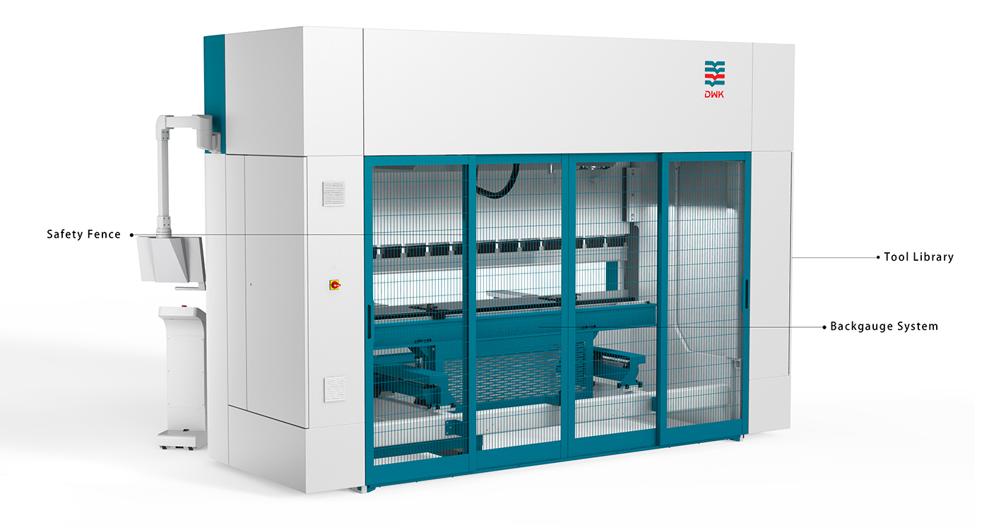
Tooling selection dictates the success or failure of your bending operation. The standard rule of thumb for V-die selection is 8 times the material thickness for mild steel. For example, bending 2mm mild steel requires a 16mm V-die opening. Bending stainless steel or thicker plate often requires increasing this ratio to 10x or 12x to prevent tooling fractures.
The punch radius directly affects the inside bend radius of your part. Selecting a punch with a radius too sharp for the material causes cracking along the bend line. Modern CNC controllers simplify this process significantly. They filter compatible punches and dies based on your input parameters. You enter the material type and thickness, and the software recommends the optimal tooling combination.
Material Thickness (Mild Steel) | Recommended V-Die Opening (8x Rule) | Minimum Inside Radius | Approximate Tonnage per Foot |
|---|---|---|---|
1.0 mm (0.039 in) | 8 mm | 1.2 mm | 4 Tons |
2.0 mm (0.078 in) | 16 mm | 2.6 mm | 7 Tons |
3.0 mm (0.118 in) | 24 mm | 4.0 mm | 10 Tons |
6.0 mm (0.236 in) | 50 mm (Use 8.5x ratio) | 8.0 mm | 18 Tons |
Load segmented tooling carefully to avoid chipping the hardened edges. Always wear heavy-duty cut-resistant gloves. Slide the upper punches into the clamping system from the side if possible. If front-loading, ensure the safety tang engages the clamp before letting go. Align the lower dies in the centering groove of the bed.
Seating the tools is a mandatory step before full-pressure operation. Bring the ram down under very low pressure. Allow the punch to enter the V-die and bottom out gently. This action forces the punches and dies to align perfectly parallel. Once the tools are fully seated under low pressure, tighten all manual clamps securely. Hydraulic clamping systems will lock the tools automatically during this phase. Never attempt to bend material without verifying the tools are fully seated, as unseated tools will shift under load and ruin the workpiece.
Accurate programming starts with precise data entry. You must input the exact material type, thickness, length, and tensile strength into the controller. Do not guess the tensile strength. Variations in material hardness drastically change the required bending force and springback calculations. A36 mild steel behaves very differently than 304 stainless steel or 5052 aluminum.
Next, select the correct punch and die profiles from the controller's tooling library. The software uses these specific tool dimensions to calculate the exact pinch point. It determines the precise ram depth required to achieve your target angle. Incorrect tooling inputs will result in severe angle deviations or machine crashes.
Programming the bend sequence requires spatial awareness. You must define the bend angles and flange lengths for each step. Plan the sequence to avoid part interference. The workpiece must not hit the machine frame, the ram, or the tooling during the folding process.
Work from the outside edges of the part inward whenever possible. Keep the bulk of the material outside the machine envelope. This strategy makes handling easier and safer for the operator. The controller will automatically calculate the X-axis backgauge positions for each programmed flange length. It will also manage the R-axis height to ensure the fingers rest at the correct elevation for the die being used.
Never execute a new program without running a digital simulation first. Modern controllers feature 2D or 3D visual simulations of the entire bending process. Watch the simulation closely on the screen.
The simulation identifies tooling collisions before they happen in reality. It highlights backgauge interference and warns you if a flange will hit the punch body. Simulation also demonstrates the optimal part handling sequence. This visual guide is invaluable for beginner operators learning how to flip and rotate complex parts between bends. It takes the guesswork out of complex multi-bend enclosures.
Air bending is the standard method for most CNC operations. In air bending, the material does not touch the bottom of the V-die. The punch presses the sheet into the die opening just far enough to achieve the desired angle. The final angle relies entirely on the precise depth of the ram descent. This method allows operators to form multiple different angles using the exact same tooling setup, saving hours of changeover time.
Contrast this with bottoming and coining. Bottoming forces the material against the sides of the V-die. Coining stamps the punch tip directly into the material at the bottom of the die. Both methods require significantly higher tonnage than air bending—often three to five times as much force. They also cause rapid tooling wear and can permanently damage the press brake bed if the tonnage limits are exceeded. Avoid bottoming unless specifically required by the engineering drawing for tight radius bends in thin materials.
Always execute the first bend on a scrap test piece of the exact same material batch. Run the program for the first step and bend the test piece. Remove the part and measure the resulting angle using a calibrated protractor or digital angle gauge.
Material springback will almost always cause the first bend to be slightly open. Calculate the difference between your target angle and the measured angle. Input this angle correction into the CNC controller. The software will apply a Y-axis offset, driving the ram slightly deeper on the next cycle to compensate for the springback. If the bend is uneven from end to end, adjust the crowning system parameters.
Beginners frequently encounter material slipping off the backgauge fingers during the ram descent. This happens when the operator fails to support the sheet horizontally. Keep the material level and apply light forward pressure against the stops until the punch pinches the sheet.
Uneven bends often result from poor material placement. Verify that the workpiece rests completely flat against all backgauge stops. If the sheet is skewed even a fraction of a millimeter, the bend line will wander. Ensure the material edges are deburred. Rough, jagged edges prevent the sheet from seating squarely against the backgauge fingers. Another common issue is the canoe effect, where the center of the bend is a different angle than the ends. This requires fine-tuning the CNC crowning table to push the center of the lower die upward.
Hydraulic press brakes present severe crushing hazards. Active safeguarding systems are mandatory. Laser safety systems project a continuous laser band just below the punch tip. If an operator's hand breaks this laser band during the fast downstroke, the machine stops instantly.
Understand the concept of the mute point. The mute point is the exact height where the ram transitions from a high-speed approach to a slow pressing speed. This usually occurs just millimeters above the material surface. At the mute point, the laser system temporarily deactivates to allow the punch to contact the metal without triggering a fault. Operators must never bypass, alter, or ignore these safety features.
Bending large panels introduces significant physical risks. As the ram descends, the material extending outside the machine folds upward rapidly. This upward motion is known as sheet whip. Sheet whip can strike the operator under the chin or break wrists if handled improperly.
Never grip the material tightly during the bend. Support the sheet from underneath with open palms. Let the material slide across your hands as it folds upward. For heavy or oversized workpieces, use sheet followers or front support arms. These mechanical aids lift the material synchronously with the bending speed. They prevent operator injury, reduce fatigue, and stop heavy sheets from reverse-bending under their own weight.
Follow these material handling rules:
Always use two operators for sheets wider than four feet.
Keep your thumbs tucked under the sheet, never resting on top.
Use magnetic squaring arms for heavy plate to assist with alignment.
Clear the swing radius of the part before pressing the pedal.
Never leave a press brake powered on and unattended. Follow a strict shutdown sequence to secure the equipment. First, lower the ram to a closed position. Rest the upper punches gently inside the lower dies. This action relieves all hydraulic pressure from the cylinders.
Leaving the ram suspended in the air relies entirely on the hydraulic valves holding pressure. Over time, valves can drift, causing the ram to drop unexpectedly. Once the tools are resting together, power down the CNC controller. Finally, shut off the main hydraulic pump and turn the main electrical disconnect to the off position.
Remove tooling carefully to prevent edge damage. Unclamp the punches and slide them out safely. Wipe down all tooling with a lightly oiled cloth before returning them to the storage rack. This prevents rust formation and maintains the hardened surfaces. Inspect the punch tips for galling, especially after bending aluminum or galvanized steel. Galling occurs when material transfers from the workpiece to the tooling, creating a rough surface that will scratch future parts. Use a fine abrasive pad to remove any galling immediately.
Clean the workstation thoroughly at the end of the shift. Use a shop vacuum or brush to clear metal dust, mill scale, and debris from the lower die holder. Pay special attention to the backgauge linear guides. Debris buildup on the linear rails destroys the bearings and ruins the long-term positioning accuracy of the machine.
When expanding a fabrication department, controller usability directly impacts training timelines. Graphical interfaces with touch-screen controls drastically reduce the time it takes to train a new operator. Visualizing the bend sequence makes abstract numerical data easy to understand.
Evaluate the trade-off between complex controllers and intuitive interfaces. High-turnover shop floors benefit immensely from offline programming software. Engineers can program and simulate the entire job in the office. They send the verified file directly to the machine. The operator simply loads the file, sets the tools as instructed by the screen, and begins bending. This removes the programming burden from beginner operators.
Investing in automated setup features justifies the initial capital expenditure through massive time savings. Automatic CNC crowning systems adjust the bed curve dynamically to guarantee straight bends over long lengths. This eliminates the need for manual shimming.
Hydraulic tool clamping reduces tool changeover times from minutes to seconds. Multi-axis backgauges allow operators to form complex, asymmetrical parts without building custom fixtures. These automated features reduce setup time, minimize operator error, and ensure consistent part quality regardless of the operator's experience level.
Audit current standard operating procedures to ensure pre-operation inspections are documented and enforced daily.
Train all operators extensively on controller simulation features to identify collisions before wasting material.
Implement a strict tooling maintenance schedule, requiring all punches and dies to be cleaned and oiled after use.
Consult with equipment manufacturers on integrating offline programming solutions to move setup tasks off the shop floor.
A: A manual press brake requires the operator to physically set mechanical stops for ram depth and backgauge position. A CNC press brake automates these axes via computerized programming, managing bending speed and pressure dynamically, which drastically improves repeatability and reduces setup time.
A: The industry standard for air bending mild steel is a V-die opening equal to 8 times the material thickness. For thicker materials or high-tensile steel, this ratio increases to 10x or 12x to prevent tooling damage.
A: Springback is the tendency of metal to return slightly to its original flat shape after bending. Modern CNC controllers use material databases and angle measurement systems to calculate and automatically over-bend the material to achieve the target angle.
A: Yes, a 100 ton machine can typically bend 1/4-inch mild steel, but the maximum bending length will be limited. Operators must consult a tonnage chart to ensure the required force per foot does not exceed the machine's capacity.
A: This is usually triggered by the laser safety system or light curtain detecting an obstruction, or the controller reaching the programmed mute point where it transitions from fast approach to slow pressing speed.


