
Please Choose Your Language
- All
- Product Name
- Product Keyword
- Product Model
- Product Summary
- Product Description
- Multi Field Search
TEL : +86-18920692288
Email : dwk0002025@163.com
Views: 0 Author: Site Editor Publish Time: 2026-09-02 Origin: Site


Precision bending is rarely limited by the raw power of the machine; it is dictated by the exact configuration of drive systems, tooling, software, and mechanical calibration. Inconsistent bend angles, unmanaged material springback, and prolonged setup times lead to high scrap rates, production bottlenecks, and compromised structural integrity in final assemblies. Achieving repeatable precision requires moving beyond baseline tonnage specifications to evaluate drive technologies, multi-axis backgauging, crowning systems, safety integrations, and industry-specific configurations. Fabricators often struggle with holding tight tolerances across varied material batches. A standard press brake might form a perfect 90-degree angle on the first test piece, only to drift by two degrees halfway through the production run. This drift stems from thermal expansion in hydraulic fluids, microscopic wear on tooling, and natural bed deflection under load. To eliminate these variables, you must configure the machine specifically for the materials you process.
Drive System Dictates Baseline Accuracy: Servo-electric models provide superior precision for thin-gauge materials, while advanced CNC hydraulic systems are required to manage variance in heavy-plate applications.
Tooling and Crowning are Non-Negotiable: Even the most advanced machine will fail tolerance checks without precision-ground tooling and automated mechanical crowning to compensate for bed deflection.
Backgauging Drives Throughput: Upgrading from standard 2-axis to 6-axis CNC backgauging drastically reduces setup time and operator error for complex, multi-bend geometries.
Standardization Mitigates Risk: Long-term precision relies heavily on standardized setup sheets, offline programming, and rigorous preventive maintenance schedules to offset operator skill gaps.
Before selecting machine options, you must define what precision means for your specific applications. Acceptable deviation margins vary wildly depending on the final assembly requirements. A structural bracket welded into a larger frame might tolerate a one-degree variance. An aerospace enclosure or a tightly fitted electrical chassis requires accuracy down to a fraction of a degree. Variations in material thickness, grain direction, and tensile strength directly impact bend accuracy. When you feed a machine a sheet of steel that is nominally 3mm thick, the actual thickness might fluctuate between 2.8mm and 3.2mm. This slight variance changes the required penetration depth of the punch to achieve the target angle. If your machine cannot detect and adjust for this variance on the fly, your scrap bin will fill up quickly.
The physical dynamics of bending change drastically as material thickness increases. Setting up a machine for thin-gauge sheet metal requires acute precision, fast ram speeds, and highly responsive backgauges. The focus is on rapid cycle times and preventing material surface damage. Operators handling 16-gauge stainless steel need a machine that reacts instantly to pedal inputs. Conversely, heavy plate metal demands massive tonnage, larger V-die openings, and robust deflection management. Thick plates amplify the natural bowing of the machine bed, making mechanical compensation systems mandatory. You cannot treat a 1/2-inch A36 steel plate the same way you treat thin aluminum.
Parameter | Thin-Gauge Sheet Metal (< 3mm) | Heavy Plate Metal (> 10mm) |
|---|---|---|
Ram Speed | High approach and return speeds required. | Controlled, slower pressing speeds to prevent cracking. |
Tooling | Acute punches, narrow V-dies, precision-ground. | Large radius punches, wide heavy-duty V-dies. |
Deflection | Minimal, easily managed by standard crowning. | Severe, requires heavy-duty automated mechanical crowning. |
Handling | Manual or light robotic handling. | Automated sheet followers and overhead cranes essential. |
The chosen bending method dictates your tooling selection, required tonnage, and setup parameters. Air bending is the modern standard on the shop floor. The punch presses the material into the V-die without bottoming out. The final angle is determined entirely by the penetration depth of the punch. This method requires less tonnage and allows you to form multiple angles with the same tooling setup. Bottoming forces the material fully into the die, requiring higher tonnage and specific tooling for every angle. Coining is an older method that stamps the material into exact conformity with the die. It demands immense tonnage and causes rapid tooling wear. For precision work today, air bending combined with advanced CNC controls is the preferred approach.
When you release bending pressure, the material naturally attempts to return to its original flat state. This phenomenon is known as springback. In air bending, managing springback is the primary hurdle to achieving accurate angles. The amount of springback depends on the material's yield strength, thickness, and the inner radius of the bend. High-tensile materials exhibit significantly more springback than mild steel. To manage this, operators must overbend the material by a calculated amount. Modern setups rely on real-time angle measurement systems. These systems use lasers or mechanical probes to measure the angle during the bending cycle. They dynamically adjust the punch depth to compensate for springback on the fly without requiring a test piece.
Fabricators often confuse absolute accuracy with repeatability. Absolute accuracy is the machine's ability to hit an exact angle on a single, isolated bend. Repeatability is the machine's ability to maintain that exact angle across a 1,000-part run under changing environmental conditions. As a hydraulic machine runs throughout a shift, the hydraulic fluid heats up, changing its viscosity. This thermal drift can alter the ram stopping position by a few microns, which translates to a fraction of a degree in the bend angle. Achieving high repeatability requires drive systems and software that actively monitor and compensate for these thermal variations.
The drive system is the heart of the machine. It dictates the baseline accuracy, energy consumption, and maintenance requirements. Selecting the right technology depends entirely on your material thickness and production volume.
Hydraulic systems remain the industry standard for versatility and high-tonnage requirements. They utilize dual hydraulic cylinders to drive the ram downward. Modern CNC hydraulic machines rely on proportional valves and independent linear scales to synchronize the cylinders. This maintains strict ram parallelism even during off-center bending. These systems can deliver massive force, making them ideal for heavy plate fabrication. The primary trade-off with pure hydraulic systems is thermal drift. The hydraulic pump runs continuously, heating the fluid over long shifts. The changing viscosity can cause slight variations in ram positioning. While advanced CNC controls compensate for this drift, it remains a factor in ultra-high-precision applications.
For high-speed, high-precision applications typically under 100 tons, servo-electric drive systems offer unmatched performance. These machines replace hydraulic cylinders with servo motors connected to ball screws or belt-and-pulley systems to drive the ram. The elimination of hydraulic fluid means zero thermal drift. The ram positioning is accurate to the micron level from the first part of the shift to the last. Servo-electric models only consume power when the ram is moving. They operate with significantly less noise and require less maintenance due to the absence of oil filters, valves, and fluid changes. The trade-offs include a limited tonnage capacity, making them unsuitable for thick plate work.
Hybrid drive systems represent the middle-ground solution. They utilize servo motors to drive individual hydraulic pumps mounted directly on each cylinder. The servo motor only spins the pump when ram movement is required. This combines the high tonnage capability of hydraulics with the thermal stability of servo-electric systems. Because the hydraulic circuit is closed and the oil volume is minimal, thermal drift is virtually eliminated. Hybrid systems offer faster response times, higher approach speeds, and greater positional accuracy than traditional hydraulic machines. They are the ideal configuration for fabricators who need to process a wide mix of materials without sacrificing precision.
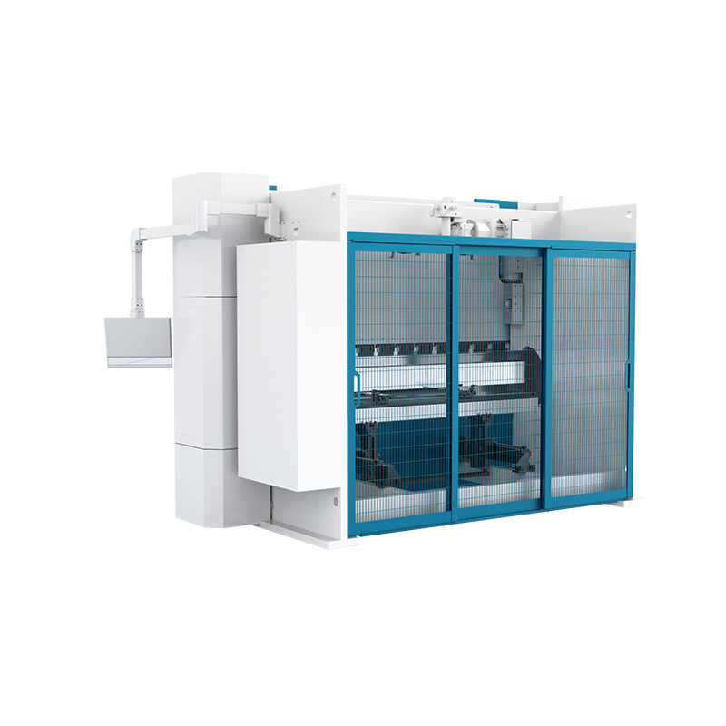
Beyond the drive system, the mechanical configuration of the machine dictates its ability to hold tight tolerances. Overlooking tooling, crowning, or backgauging will render a high-end drive system useless.
Specifying the correct tonnage is the first step in machine configuration. Tonnage requirements are calculated based on material type, thickness, bend length, and the chosen V-die opening. A standard rule of thumb is to use a V-die opening that is 8 times the material thickness for mild steel, and 10 to 12 times for stainless steel or high-tensile materials. A common mistake on the shop floor is over-specifying the bed length while under-specifying the tonnage per foot. If you buy a 14-foot machine to bend 10-foot parts simply to have extra room, you introduce unnecessary bed deflection. A longer bed naturally bows more under load. You should size the bed length as closely as possible to your maximum part length to maximize rigidity and minimize deflection.
Traditional planed tooling is insufficient for high-tolerance work. Precision-ground tooling is manufactured to exact dimensional tolerances. This ensures that the punch tip and die shoulder are perfectly consistent across their entire length. When you load precision-ground segments into the machine, they align flawlessly, eliminating the need for manual shimming. To maximize throughput, integrate hydraulic or pneumatic quick-clamping systems. Manual clamping requires operators to tighten individual set screws, which is time-consuming and prone to uneven seating. Quick-clamping systems seat and align the tooling automatically with the push of a button. This reduces setup times from hours to minutes and ensures the tools are perfectly parallel to the bed.
When the ram presses down, the side frames of the machine stretch slightly, and the center of the bed bows downward. This deflection causes the punch to penetrate less in the center of the machine than at the edges. The result is a bend angle that is open in the middle and tight on the ends, commonly called the "canoe" effect. To counteract this, you must configure the machine with a CNC-controlled mechanical crowning system. Mechanical crowning uses a series of precision wedges built into the lower die holder. The CNC control calculates the expected deflection based on the material thickness, length, and tonnage. It automatically drives a motor to adjust the wedges. This pushes the center of the bed upward, keeping the die perfectly parallel to the punch under load. Automated crowning completely replaces manual shimming.
The backgauge positions the material under the punch. Its configuration directly impacts your ability to form complex parts accurately and quickly. Backgauge requirements should be broken down by part complexity.
2-Axis (X, R): Controls the depth (X) and height (R) of the gauge fingers. Suitable for basic, straight flanges on flat parts.
4-Axis (X, R, Z1, Z2): Adds independent left/right movement (Z1, Z2) for the gauge fingers. Essential for bending parts of varying widths or when staging multiple tooling setups along the bed.
6-Axis (X1, X2, R1, R2, Z1, Z2): Provides completely independent movement for each gauge finger in all directions. Required for asymmetrical parts, complex geometries, and taper bending where the flange is not parallel to the bend line.
Upgrading to a 6-axis system drastically reduces operator handling. Instead of manually adjusting stops or struggling to align awkward parts, the backgauge fingers position themselves exactly where needed.
Modern safety guarding must protect the operator without introducing cycle-time bottlenecks. Traditional light curtains often force operators to slow down or mute the safety system entirely when forming complex flanges that break the light beam. Configuring modern laser safety systems resolves this issue. These systems project a protective laser zone mere millimeters below the punch tip. They allow the ram to close at high speed until it is just above the material, at which point it drops into pressing speed. This ensures strict operator protection while maintaining maximum machine throughput.
The CNC control is the brain of the operation. Modern 3D graphical controls allow operators to visualize the entire bending sequence before stepping on the pedal. The software simulates the part, the tooling, and the machine frame to detect potential collisions. If a flange will hit the ram on the third bend, the software flags it immediately. To truly optimize setup time, integrate offline programming software. This moves the setup process from the shop floor to the engineering office. Engineers can import 3D CAD models, select the tooling, generate the bend sequence, and send a complete, verified program directly to the machine.
Different manufacturing sectors demand entirely different machine setups. A configuration that excels in a sheet metal job shop will fail miserably in a heavy equipment manufacturing facility.
Automotive part manufacturing focuses on high-volume production, complex geometries, and rapid cycle times. The materials are often high-strength, thin-gauge steels or aluminum alloys. An automotive press brake requires a highly dynamic drive system, typically servo-electric or hybrid, to achieve maximum approach and return speeds. A 6-axis backgauge is mandatory to handle the asymmetrical shapes of automotive brackets and chassis components. Furthermore, these machines are frequently integrated with robotic material handling systems. Real-time angle correction is critical in this setup, as the automated cell must compensate for material batch variations without human intervention.
Manufacturing equipment for the mining and construction sectors involves handling high tensile strength materials, such as Hardox or Weldox, in extreme thicknesses. A heavy duty mining press brake is built purely for massive tonnage and structural rigidity. These setups often utilize tandem CNC hydraulic configurations, where two large machines are synchronized to act as one continuous bed for bending exceptionally long plates. Setup requirements include heavy-duty variable V-dies that can open and close to accommodate different plate thicknesses without requiring physical tool changes. Robust mechanical crowning is non-negotiable due to the extreme deflection forces. Automated sheet followers are required to support the heavy plate as it bends, preventing dangerous material whip.
Prototyping and custom job shops operate in a high-mix, low-volume environment. They might bend ten different parts in a single shift, requiring rapid changeovers and maximum flexibility. A CNC prototyping press brake prioritizes software and tooling agility over raw speed or tonnage. The setup requires highly intuitive 3D touchscreen controls that allow operators to quickly draw parts and generate bend sequences at the machine. Universal quick-clamp tooling systems are essential to swap punches and dies in minutes. Deep integration with offline programming software allows the shop to move seamlessly from a customer's CAD file to a finished bent part on the same day.
Even the most perfectly configured machine will produce scrap if the operational workflows are flawed. Precision bending requires strict adherence to standardized procedures and rigorous maintenance.
A standardized operational sequence prevents errors and ensures consistency across different operators and shifts. The workflow should follow a strict order:
Tooling Inspection: Visually inspect punches and dies for wear, galling, or debris before loading. A single metal chip in the die holder will throw off the angle.
Program Loading: Load the verified program from the network and review the 3D simulation for collision warnings.
Tool Seating: Load the tooling according to the setup sheet and actuate the quick-clamping system. Bring the ram down under low pressure to properly seat the punch into the die.
First-Article Test: Execute the first bend on a scrap piece of the actual production material.
Springback Adjustment: Measure the angle and input the deviation into the CNC control. The software will automatically adjust the punch penetration depth for the production run.
Relying on operator memory is a critical failure point in precision fabrication. When an operator guesses which tooling was used on a previous run or where the backgauge fingers were positioned, scrap is inevitable. Long-term precision relies on digital setup sheets integrated directly into the CNC control. These sheets must explicitly detail the exact punch and die part numbers, the precise location of the tooling along the bed, the required backgauge finger positions, and the step-by-step bend sequencing. By standardizing this data, any operator can step up to the machine and replicate the exact setup used six months prior.
The fabrication industry faces a severe shortage of master fabricators who understand the nuances of metal forming. Relying on tribal knowledge is no longer a viable business strategy. Investing in advanced CNC controls, offline programming, and real-time angle measurement systems directly offsets the lack of experienced operators. When the machine calculates the bend allowance, manages the crowning, and measures the springback automatically, the operator's role shifts from a master craftsman to a machine supervisor. This allows shops to achieve high precision with less experienced personnel.
Precision degrades over time without rigorous preventive maintenance. You must establish a baseline maintenance schedule tailored to high-tolerance work. Key calibration tasks include:
Gib Clearance Checks: The guides that keep the ram moving perfectly vertical wear over time. Regularly check and adjust the gib clearances to prevent ram twist.
Hydraulic Fluid Analysis: For hydraulic and hybrid systems, degraded oil causes valve sticking and pressure fluctuations. Perform regular fluid analysis and replace filters on schedule.
Backgauge Laser Alignment: Backgauge fingers sustain impacts from heavy material. Periodically verify their alignment using laser measurement tools to ensure they remain perfectly parallel to the bend line.
Tooling Calibration: Measure punches and dies periodically to ensure they have not lost their dimensional accuracy due to radius wear or compression.
Audit your current scrap rates to isolate material variance from machine deflection issues.
Calculate exact tonnage requirements based on your thickest, highest-tensile parts to avoid over-specifying bed length.
Standardize all tooling to precision-ground profiles equipped with hydraulic quick-clamping systems.
Implement offline programming software to move setup verification off the shop floor and into the engineering office.
A: Yes, retrofitting is possible but limited. You can upgrade the CNC control, install precision quick-clamping systems, and add new backgauges. However, you cannot easily fix inherent mechanical wear in the ram guides or the lack of an automated CNC crowning system, which are critical for true precision.
A: A 6-axis CNC backgauge is ideal for prototyping. Because prototyping involves high-mix, complex, and often asymmetrical parts, independent control of each gauge finger in the X, R, and Z axes allows operators to support odd geometries without building custom fixtures.
A: Under heavy tonnage, the machine bed naturally bows downward in the center. Automatic CNC crowning uses motor-driven wedges to push the center of the bed upward, perfectly counteracting the deflection. This ensures the die remains parallel to the punch, creating a consistent angle across the entire bend length.
A: Air bending requires the punch to press the material into the V-die without touching the bottom, relying on punch depth for the angle. It uses less tonnage and allows multiple angles per tool. Bottoming forces the material fully into the die, requiring higher tonnage and specific tooling for every desired angle.
A: Modern laser safety systems actually improve cycle speed. They project a protective zone just below the punch, allowing the ram to descend at maximum approach speed until it is millimeters from the material before dropping into a safe pressing speed, eliminating unnecessary slow-downs.
A: Calibration frequency depends on usage, but high-precision operations should verify backgauge alignment and ram parallelism monthly. Comprehensive mechanical inspections, including gib clearance adjustments and hydraulic system checks, should be performed annually or bi-annually by a certified technician.


